
Factory Supply Single Phase Pole Mounted Transformer 15Kv to200V/240V
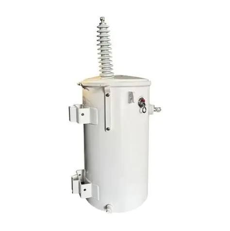
Factory Supply Single Phase Pole Mounted Transformer 15Kv to200V/240V
Main Parameters
Parameter | Specification |
Rated power | 167 kVA at 240 V reference design; 25–250 kVA available |
Type | Single-phase, two-winding, oil-immersed pole-mounted distribution transformer |
Frequency | 50 Hz or 60 Hz, fixed at design |
Primary voltage | 15,000 V nominal, Um 17.5 kV (IEC), 15 kV class (ANSI) |
Taps | ±2 × 2.5%, off-circuit, five positions: 15,750 / 15,375 / 15,000 / 14,625 / 14,250 V |
Secondary voltage | 240 V with a 200 V tap; two-wire with a neutral on the three-wire version |
Polarity | Additive |
Rated current | ≈ 11.1 A on the HV side; ≈ 696 A at 240 V, ≈ 696 A at 200 V |
Capacity at 200 V | ≈ 139 kVA, limited by the rated secondary current rather than by the winding |
Impedance | 2.5% at 75 °C; 2.0–3.0% according to the fault level on the spur |
No-load loss | ≈ 300 W |
Load loss | ≈ 1,750 W at 85 °C, full load |
Full-load efficiency | ≈ 98.8% |
Temperature rise | 65 °C average winding rise; 55 °C rise version for hot sites |
Cooling | ONAN |
Insulating fluid | Mineral oil to IEC 60296 / ASTM D3487, ≈ 150 kg; ester fluid on request |
Core | Grain-oriented silicon steel, two-limb, mitred step-lap joints |
Windings | Copper HV layer winding with graded insulation, copper LV winding; aluminium on request |
Tank | Welded steel, corrugated wall, hermetically sealed, pole bracket and lifting lugs |
Insulation level | 95 kV lightning impulse; 38 kV power-frequency withstand to IEC Um 17.5 kV, 34 kV per ANSI 15 kV class |
HV bushing | Porcelain, single bushing with the tank grounded; two-bushing version on request |
LV terminals | Two stud terminals under a bolt-on cover, rated for the ≈ 696 A secondary current |
Protection | Conventional with upstream cutout and arrester, or CSP with internal HV fuse, arrester and secondary breaker |
Fittings | Pressure relief device, drain plug, fill plug, lifting lugs, earthing lug, pole bracket, arrester mounting provision |
Sound level | ≤ 48 dB(A) at 1 m, NEMA test distance |
Mass | ≈ 580 kg complete; oil ≈ 150 kg |
Standards | IEC 60076-1, -2, -3, -5 for insulation and testing; ANSI/IEEE C57.12.00, C57.12.20, C57.12.90 for pole-mount construction and protection conventions |
Tests | Routine: winding resistance, ratio and polarity, no-load loss and current, load loss and impedance, applied and induced voltage, oil breakdown. Type: impulse, temperature rise, sound level |
Loss values are design figures. Each unit ships with a routine test report carrying the measured no-load loss, load loss, impedance and ratio for that serial number, which is what the loss calculation on a rural feeder should use.
Product Description
The 15 kV primary is the part that has to be designed rather than assembled. A 95 kV impulse level and a 38 kV applied potential mean a graded HV winding, oil ducts with real spacing, a bushing with adequate creepage and lead routing that keeps the field off the tank wall. A unit built by scaling a 15 kV distribution platform up to this ratio will pass a routine test and still fail on the first switching surge; the insulation has to be built for the class.
The secondary arrangement needs explaining, because 200/240 V is not two separate windings. It is a 240 V winding with a 200 V tap, so the unit can be set to deliver either voltage at the terminals. The catch is capacity: the winding's rated current is fixed, so at 200 V the unit delivers about 139 kVA rather than 167 kVA. That is not a defect, it is arithmetic — 696 A at 200 V is 139 kVA however the nameplate reads. If the site runs at 200 V permanently, specify a dedicated 200 V winding so the full rating is available at that voltage; the tap is for sites that shift between the two.
Impedance is 2.5%, which at 240 V holds prospective fault current near 28 kA. On a rural spur with a 25 or 50 kVA upstream fuse, that is a workable number; on a long line with weak fault current, protection coordination needs checking against the actual source impedance rather than the transformer alone.
Mechanically the unit is the standard pole package: a corrugated sealed tank under vacuum, a pole bracket, lifting lugs, additive polarity, and a single HV bushing with the tank grounded. At 580 kg it is a two-person set with a line truck, which matters on a rural crew with limited equipment.
On factory supply: this ratio is not stocked anywhere, so the order is a build slot rather than a shelf pick. What that means in practice is a drawing approval before production, a defined tap and secondary arrangement on that drawing, a per-unit test report, and a packing list that matches the nameplates. Lead time runs with the production schedule rather than a catalogue, and the buyer should expect to sign off the outline drawing — particularly the pole bracket dimensions and the cable entry side — before the core is cut.
Core Uses
The unit steps 15 kV down to a two-wire 200 V or 240 V single-phase supply. Five uses account for most orders on this ratio.
• Rural electrification on 15 kV feeders. Village clusters and scattered homes where a three-phase extension is not justified.
• Farm and irrigation service. House, barn, well pump and workshop loads from one pole mount.
• Small commercial premises. Shop, welder, compressor or dryer on a single-phase service.
• Utility spares and standard stock. A defined rating held for storm replacement on a 15 kV network.
• Replacement of legacy units. Old transformers with the same ratio swapped onto the existing pole and service.
Application Scenarios
This unit belongs where the feeder is 15 kV and the service is single-phase at 200 V or 240 V. The table maps the situations that generate most enquiries.
Scenario | Typical load | Why this unit fits |
Rural village supply on 15 kV | Homes, shops, small pumps | Serves a load pocket without extending a three-phase main; 95 kV class matches the feeder |
Farm and well pumping | 240 V pump motor, house and barn loads | 240 V runs single-phase motors directly; taps correct line voltage on a long spur |
Legacy 200 V networks | Older service panels at 200 V | 200 V tap keeps existing equipment in service; dedicated 200 V winding where the network is fixed |
Small commercial premises | Shop, welder, compressor, lighting | One service covers the whole load at a single voltage |
Utility stock and storm replacement | Spares for a 15 kV network | Standard rating, 580 kg, set by one crew, with per-unit test documentation |
Isolated facilities | Telecom, water, small industrial loads | Sealed tank and no serviceable parts suit unattended sites |
Two limits are worth stating. A single-phase unit cannot supply a three-phase load at either voltage, and 167 kVA is the practical ceiling for a pole mount — above that the weight and the fault contribution argue for a pad-mounted unit. And a 200 V tap is not a substitute for the correct ratio: if the whole network is 200 V, specify the winding rather than running a 240 V unit de-rated.
Product Features
On this ratio, most of the value is in insulation, the fixed secondary arrangement and the documentation that comes with a factory build.
• 95 kV BIL built for the class. Graded HV winding, real oil duct spacing and bushing creepage, impulse-tested rather than scaled from a lower platform.
• 240 V with a 200 V tap. Both voltages available at the terminals, with the capacity at 200 V stated honestly at about 139 kVA.
• Measured losses per unit. Around 300 W no-load and 1,750 W load loss, on a serial-numbered report.
• Sealed corrugated tank. Vacuum filled, no conservator or breather, nothing to service between inspections.
• Copper windings both sides. Lower hot-spot temperature and better short-circuit withstand than an aluminium build.
• CSP or conventional protection. Internal fuse, arrester and secondary breaker for a self-protected pole, or a plain unit protected at the cutout.
• Five tap positions. 14,250–15,750 V covers the spread on a long 15 kV spur.
• Drawing approval before production. Outline, bracket and connection drawings signed off, then a test report and packing list per unit.
Questions Buyers Ask
Question | Answer |
Does 200 V mean a separate winding? | On the standard build it is a tap on the 240 V winding, so capacity at 200 V drops to about 139 kVA at 167 kVA nameplate. A dedicated 200 V winding is available where the network is fixed at that voltage. |
Is 15 kV the same class as 13.8 kV? | No. Fifteen kilovolts takes a 95 kV impulse level and a 17.5 kV Um, against 95 kV and 15 kV class at 13.8 kV — the ratio and the insulation both differ, so the units are not interchangeable. |
Why is the unit so heavy for a single-phase rating? | At 580 kg most of it is core, copper and oil for a 167 kVA winding plus a 95 kV insulation structure. Weight is roughly a proxy for how much material is in the magnetic and dielectric design. |
Can it be paralleled with an existing unit? | Only with the same ratio, polarity, tap position and impedance. Adding a 2.5% unit alongside a 4% unit is a common mistake on rural networks and it costs a fuse. |
What does factory supply include? | The transformer as specified, routine tests per IEC 60076-1, nameplate, test report, export packing and loading list. Freight, insurance and duties depend on the incoterm. |
What is needed for the offer? | Rating, primary voltage and taps, 200 V or 240 V secondary (or both), frequency, CSP or conventional, quantity, altitude and ambient, destination port. |
Send the feeder voltage, the service voltage the customers actually have, and the largest single load on the pole. On this ratio those three answers decide the winding, the tap setting and whether 167 kVA is enough — and they cost nothing to put in the first email.