
High Quality Single Phase Pole Mounted Transformer 34.5Kv to 200V/400V
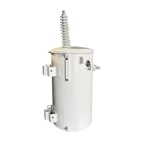
High Quality Single Phase Pole Mounted Transformer 34.5Kv to 200V/400V
Main Parameters
Parameter | Specification |
Rated power | 75 kVA reference design; 25–167 kVA available |
Type | Single-phase, two-winding, oil-immersed pole-mounted distribution transformer |
Frequency | 60 Hz standard; 50 Hz as a separate design |
Primary voltage | 34,500 V nominal, 34.5 kV class |
Taps | ±2 × 2.5%, off-circuit, five positions: 36,225 / 35,362 / 34,500 / 33,637 / 32,775 V |
Secondary voltage | Two 200 V sections; parallel connection 200 V, series connection 400 V |
Polarity | Additive |
Rated current | ≈ 2.2 A on the HV side; ≈ 375 A at 200 V, ≈ 188 A at 400 V |
Impedance | 2.5% at 75 °C; 2.0–3.0% according to the fault level on the spur |
No-load loss | ≈ 190 W |
Load loss | ≈ 900 W at 85 °C, full load |
Full-load efficiency | ≈ 98.6% |
Temperature rise | 65 °C average winding rise; 55 °C rise version for hot sites |
Cooling | ONAN |
Insulating fluid | Mineral oil to ASTM D3487 / IEC 60296, ≈ 95 kg; ester fluid on request |
Core | Grain-oriented silicon steel, two-limb, mitred step-lap joints |
Windings | Copper HV layer winding with graded insulation, copper LV sheet winding in two sections; aluminium on request |
Tank | Welded steel, corrugated wall, hermetically sealed, pole bracket and lifting lugs |
Insulation level | 150 kV lightning impulse, 70 kV power-frequency withstand at 34.5 kV class |
HV bushing | Porcelain, 34.5 kV class, single bushing with the tank grounded; two-bushing version on request |
LV terminals | Four stud terminals plus neutral link, marked for parallel or series connection, rated for the ≈ 375 A secondary current |
Protection | Conventional with upstream cutout and arrester, or CSP with internal HV fuse, arrester and secondary breaker |
Fittings | Pressure relief device, drain plug, fill plug, lifting lugs, earthing lug, pole bracket, arrester mounting provision |
Quality control | Tank tightness test under pressure, oil breakdown ≥ 60 kV before filling, dimensional check against the approved drawing, paint film thickness measurement |
Sound level | ≤ 45 dB(A) at 1 m, NEMA test distance |
Mass | ≈ 380 kg complete; oil ≈ 95 kg |
Standards | IEEE C57.12.00, C57.12.20, C57.12.90; IEC 60076-1 reference where the project specifies it (Um 36 kV would then require 170 kV impulse) |
Tests | Routine: winding resistance, ratio and polarity in both connections, no-load loss and current, load loss and impedance, applied and induced voltage, oil breakdown. Type: impulse, temperature rise, sound level |
Loss values are design figures. Each unit ships with a routine test report carrying the measured no-load loss, load loss, impedance and ratio for that serial number, tested in both secondary connections where the build is dual-voltage.
Product Description
The primary is the demanding half. A 34.5 kV class winding needs a 150 kV impulse level and a 70 kV applied potential, which means graded insulation, wider oil ducts, a 34.5 kV bushing with real creepage, and lead routing that keeps the field off the tank wall. If the project instead invokes IEC at Um 36 kV, the impulse level rises to 170 kV — a different insulation structure and a different price. Getting this straight at the enquiry stage avoids a unit that passes its factory test and fails the buyer's specification review.
The secondary is two 200 V sections with a set of terminals brought out. Connected in parallel, the unit delivers 200 V at about 375 A. Connected in series, it delivers 400 V at about 188 A. The kVA is the same either way, because the winding's current limit does not change — only the voltage and the current split do. That has an important consequence: the connection is a site decision, and it must be made before the service cable is sized.
This is worth being blunt about, because it is the most common mistake on dual-secondary units. A crew that lands the terminals in parallel onto a 400 V load will see roughly half voltage at double current capability, which usually means a stalled motor and a burnt contactor. The terminal cover should carry a clear diagram, the connection should be recorded on the nameplate, and the commissioning sheet should state which link position was used.
Impedance is 2.5%, which puts prospective fault current near 7.5 kA at 400 V and near 15 kA at 200 V. Both are modest, and on a 34.5 kV rural spur the upstream fuse is usually the coordination reference rather than the transformer.
Mechanically the unit is the standard pole package: sealed corrugated tank under vacuum, pole bracket, lifting lugs, additive polarity, single HV bushing with the tank grounded. At about 380 kg it is a two-person set with a line truck.
Now "high quality", in terms a buyer can check. It is not an adjective on a brochure; it is a set of measurements. Tank tightness held under pressure before filling, oil breakdown above 60 kV, no-load and load loss measured on every unit rather than sampled, paint film thickness measured rather than assumed, dimensions checked against the approved outline, and a nameplate that matches the test report. A factory that does those five things consistently is producing a quality unit, whether or not it uses the word.
Core Uses
The unit steps 34.5 kV down to a single-phase 200 V or 400 V supply. Five uses account for most orders on this ratio.
• Irrigation and pump blocks. 400 V single-phase pump motors on a 34.5 kV lease or farm feeder.
• Farm process loads. Grain dryers, fans, conveyors and shop equipment at 400 V.
• Oil and gas lease sites. Pump jack controls, instrumentation, lighting and quarters, often on unattended poles.
• Small industrial sites on 34.5 kV spurs. A workshop or plant load too small for a three-phase service.
• Utility replacement stock. The spare that gets a rural feeder back on after a storm.
Application Scenarios
This unit belongs where the feeder is 34.5 kV and the load is single-phase at 200 V or 400 V. The table maps the situations that generate most enquiries.
Scenario | Typical load | Why this unit fits |
Irrigation pumping on 34.5 kV | 400 V single-phase pump motors, 5–30 kW | Series connection gives 400 V for the pump stock; 150 kV class matches the feeder |
Grain drying and farm process | Dryers, fans, conveyors | 400 V single-phase with capacity for seasonal peaks; taps correct sagging line voltage |
Oil and gas lease sites | Pump jack controls, lighting, quarters | CSP option and sealed tank suit unattended poles |
Legacy 200 V equipment | Older pumps, welders, lighting | Parallel connection gives 200 V without a second transformer |
Small industrial sites | Workshop, compressor, lighting | A single-phase service where three-phase is not justified |
Storm and replacement programmes | Utility spares on a 34.5 kV network | Standard rating, 380 kg, set by one crew, with per-unit test documentation |
Two limits are worth stating. A single-phase transformer cannot supply a three-phase load, and 34.5 kV single-phase service is unusual enough that the utility may have its own connection standard — the terminal arrangement should be agreed with them rather than assumed. And where the load is a large motor, the starting method matters more than the kVA; 188 A at 400 V is a modest rated current, but a direct-on-line start will still dip the spur.
Product Features
These are the points that make a 34.5 kV pole mount hold up in service, and that a buyer can verify before shipment.
• 150 kV BIL built for the class. Graded HV winding, adequate oil ducts, 34.5 kV bushing creepage, impulse-tested rather than scaled from a lower platform.
• Dual secondary, clearly marked. Two 200 V sections with terminals and a diagram for parallel (200 V, 375 A) or series (400 V, 188 A); both connections tested at the factory.
• Measured losses per unit. Around 190 W no-load and 900 W load loss, on a serial-numbered report rather than a catalogue figure.
• Tank tightness verified. Pressure hold before filling, so a unit does not arrive with a slow leak under the paint.
• Oil tested before filling. Breakdown strength at 60 kV or better, with the certificate attached to the test report.
• Sealed corrugated tank. Vacuum filled, no conservator or breather, nothing to service between inspections.
• CSP or conventional protection. Internal fuse, arrester and secondary breaker for a self-protected pole, or a plain unit protected at the cutout.
• Paint measured, not assumed. Film thickness checked against the specified system, with the reading recorded on the inspection sheet.
Questions Buyers Ask
Question | Answer |
How does 200/400 V work on one unit? | Two 200 V secondary sections. In parallel the unit gives 200 V at about 375 A; in series, 400 V at about 188 A. The kVA stays the same because the current limit stays the same. |
Can the connection be changed on site? | Yes, at the terminals, but it must be done deliberately and recorded. Landing a parallel connection onto a 400 V load is the most common failure on dual-secondary units. |
Is 150 kV BIL correct for 34.5 kV? | Yes for the ANSI 34.5 kV class, with 70 kV applied potential. If the project invokes IEC at Um 36 kV, the impulse level becomes 170 kV — a different insulation design and price. |
What does high quality mean here? | Tank tightness tested under pressure, oil at 60 kV breakdown or better, losses measured on every unit, paint thickness measured, dimensions checked against the drawing, and a nameplate that matches the test report. |
How many homes will 75 kVA serve? | Five to eight at diversified demand, fewer where heating or pumping loads dominate. On irrigation duty, size on the largest motor rather than on the number of connections. |
What is needed for the offer? | Rating, primary voltage and taps, 200 V or 400 V connection (or both), frequency, CSP or conventional, test standard, quantity, altitude and ambient, destination port. |
Ask for the connection diagram, the tightness test record and the oil certificate before the unit ships. On a 34.5 kV dual-secondary build those three documents decide whether the installation goes in cleanly, and they cost nothing to request at the quotation stage.